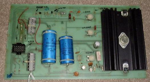
How to test a Space Invaders/SI Deluxe Power Supply
(Or any other game that uses the Midway A082-90400-x000 Power Supply)
(C) 2000, 2003 Elektron Forge, All Rights Reserved
Basic Tests:
Step 1: Apply power, check for blowing fuses.
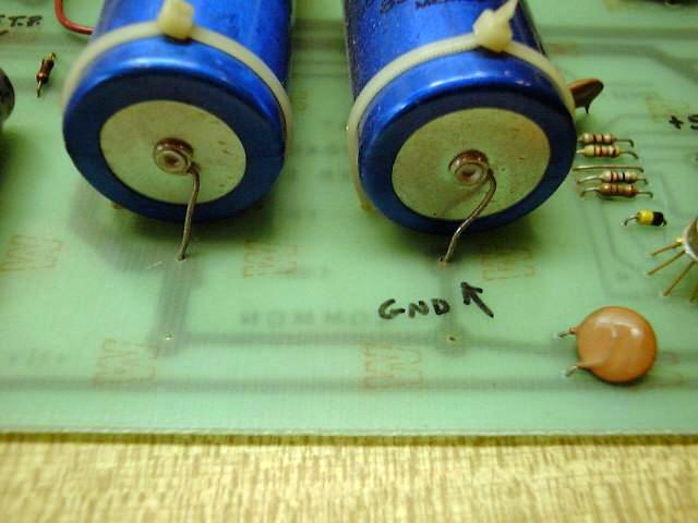
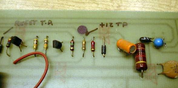
Step 2: Connect the negative (black) lead of your voltmeter here (set your meter to at least the 20VDC range).
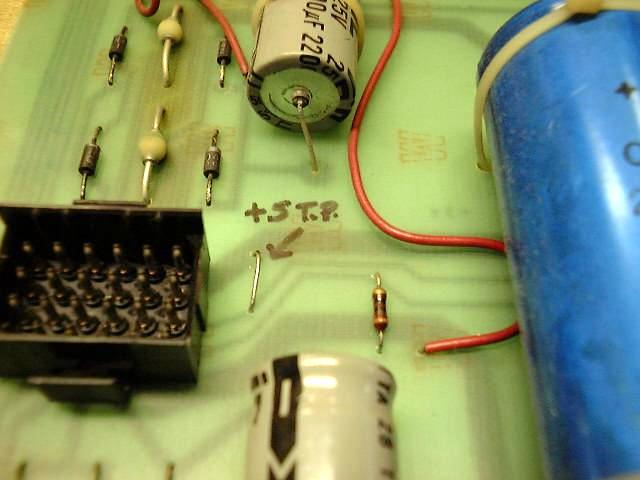
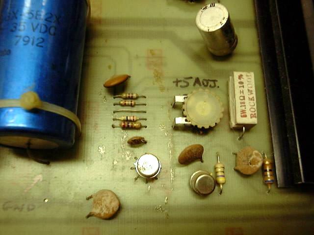
Step 3: Test the +5V line. Connect the positive (red) lead of your voltmeter here. If needed, adjust the +5V line using this pot.
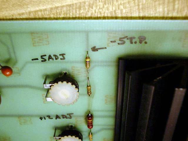
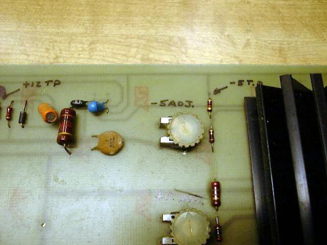
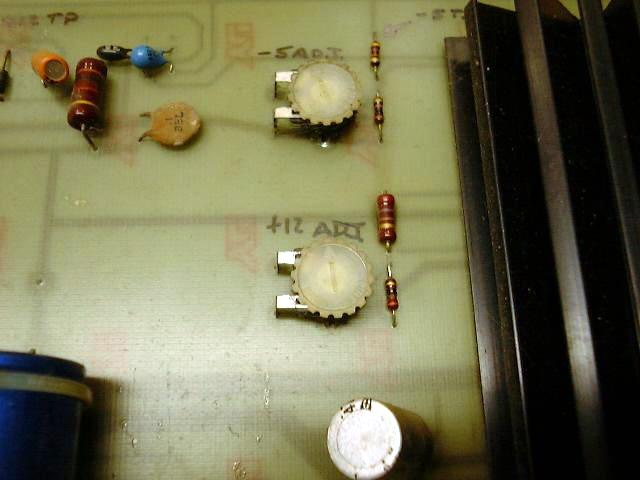
Step 4: Test the -5V line. Connect the positive lead of your voltmeter here. If needed, adjust the -5V line using this pot.
Step 5: Test the +12V line. Connect the positive lead of your voltmeter here. If needed, adjust the +12V line using this pot.
Step 6: Test the +18V line (this is for the sound amplifier). Measure it across the 1000uF capacitor. There is no adjustment.
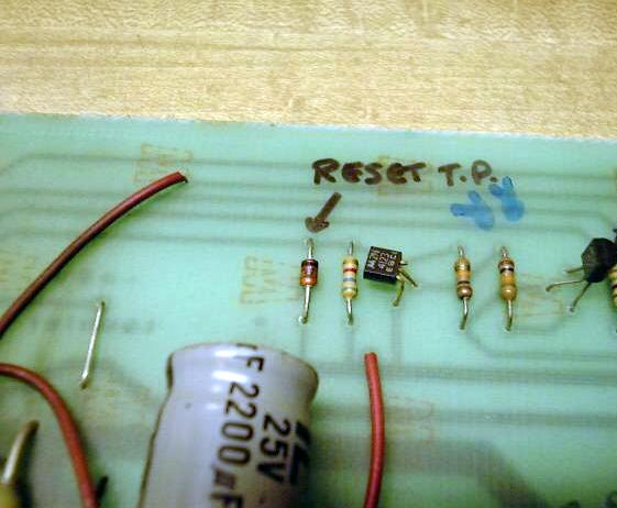
Step 7: Test the RESET signal. Connect the positive lead of your voltmeter here. With the power on, it should be 0.5V or less.
Intermediate Tests (This only works if you have a digital meter, analog meters get confused)
Step 8: Repeat Step 3, except set the meter for AC measurements. The ripple voltage should be 50mV or less.
Step 9: Repeat Step 4, except set the meter for AC measurements. The ripple voltage should be 50mV or less.
Step 10: Repeat Step 5, except set the meter for AC measurements. The ripple voltage should be 50mV or less.
Step 11: Repeat Step 6, except set the meter for AC measurements. The ripple voltage should be 50mV or less.
Advanced Tests
Step 12: Using an oscilloscope set for 1V/div and 1msec/div, verify that after powering up, the RESET signal reaches at least 3.0V before settling to less than 0.5V in about 8 msec.
Step 13: With the power off, disconnect the motherboard and game PCBs from the harness. Leave the power connector to the power regulator PCB installed.
Step 14: Verify suitable +5V range adjustment using a 5 Ohm, 10W load resistor across the 5V line.
Step 15: Verify suitable +12V range adjustment using a 47 Ohm, 10W load resistor across the 12V line.
Step 16: Verify suitable -5V range adjustment using a 47 Ohm, 1W load resistor across the -5V line.
Last updated on 2/25/06